This model is based on the Third Street Bridge (or Lefty O’Doul Bridge), which connects Mission Bay to China Basin in San Francisco, right next to the ballpark. It was designed by Joseph Strauss (the engineer for the Golden Gate Bridge) and opened in 1933 and is an example of a bascule bridge.
I was fortunate to have access to actual blueprints for the Third Street Bridge through the Stanford Library’s Joseph Strauss Bridge Plans collection, so I didn’t have to try to work out the dimensions by staring at photos.


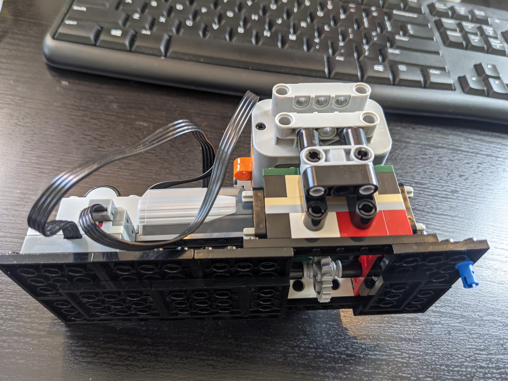
I started with miniature 2D prototype to get a feel for how the movement works and to see if I could get away with using 3-4-5 triangles.
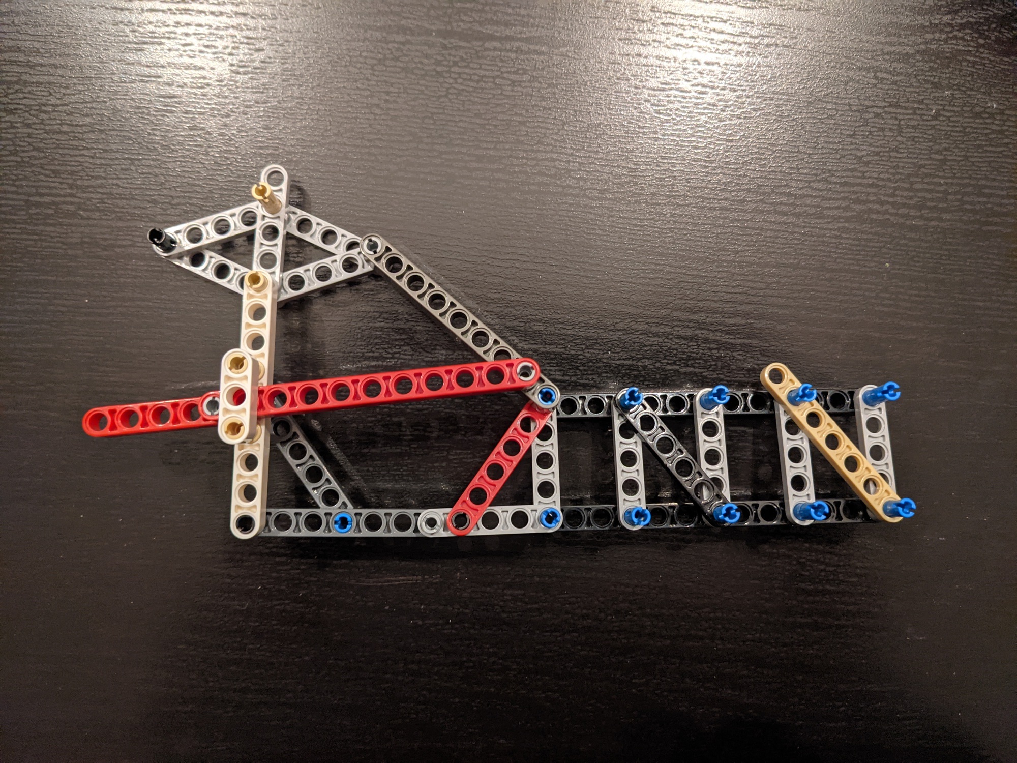
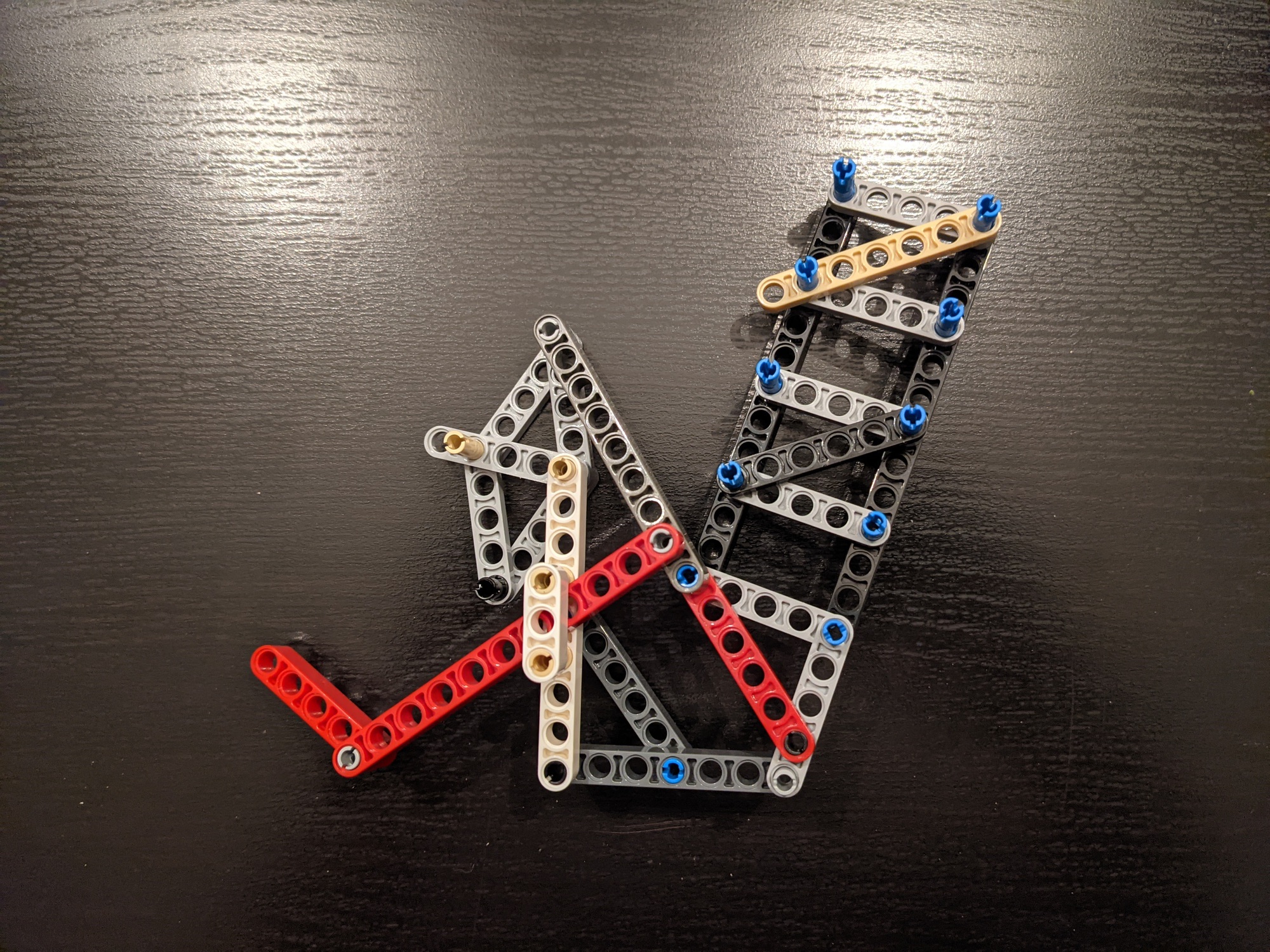


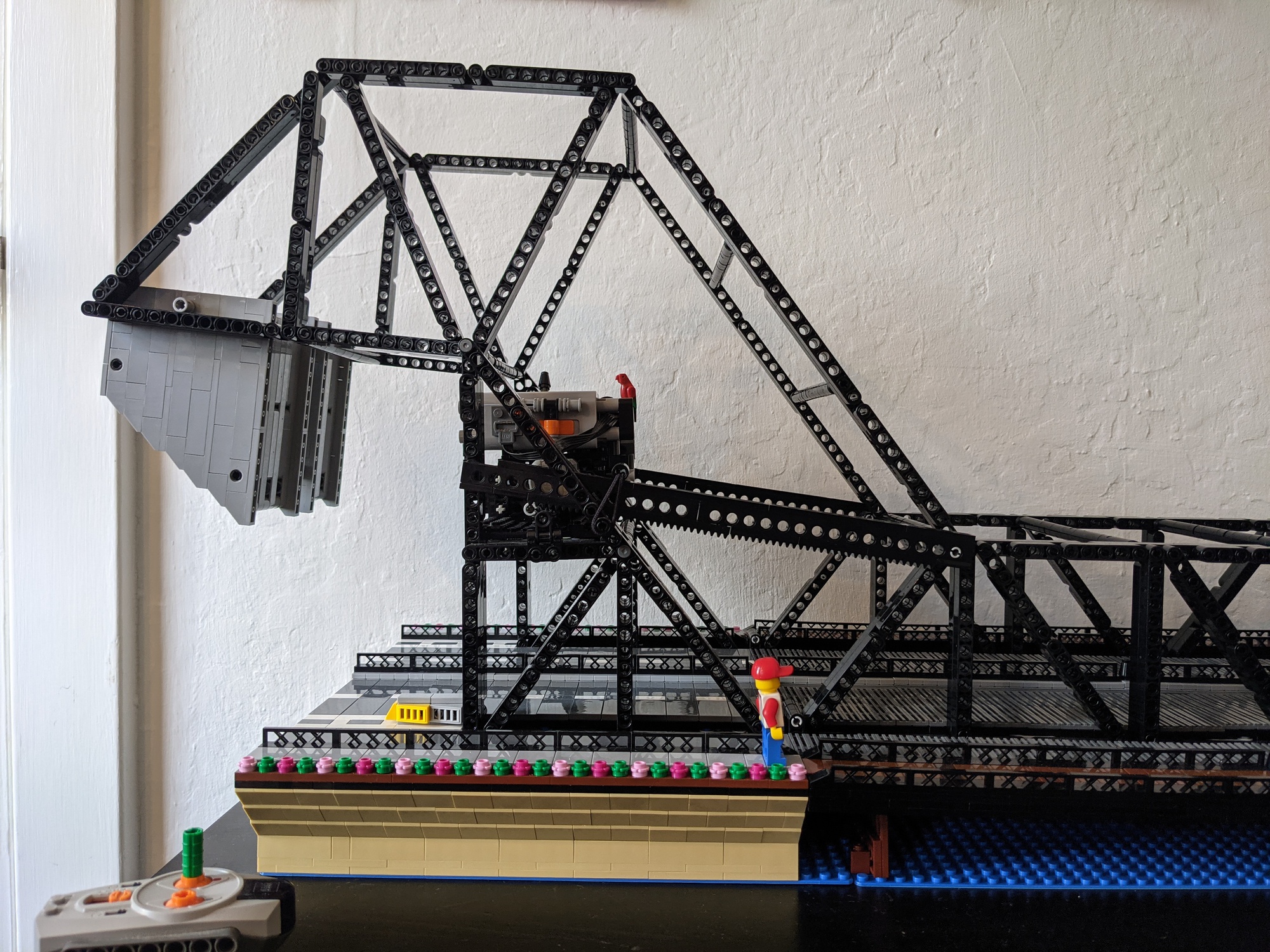
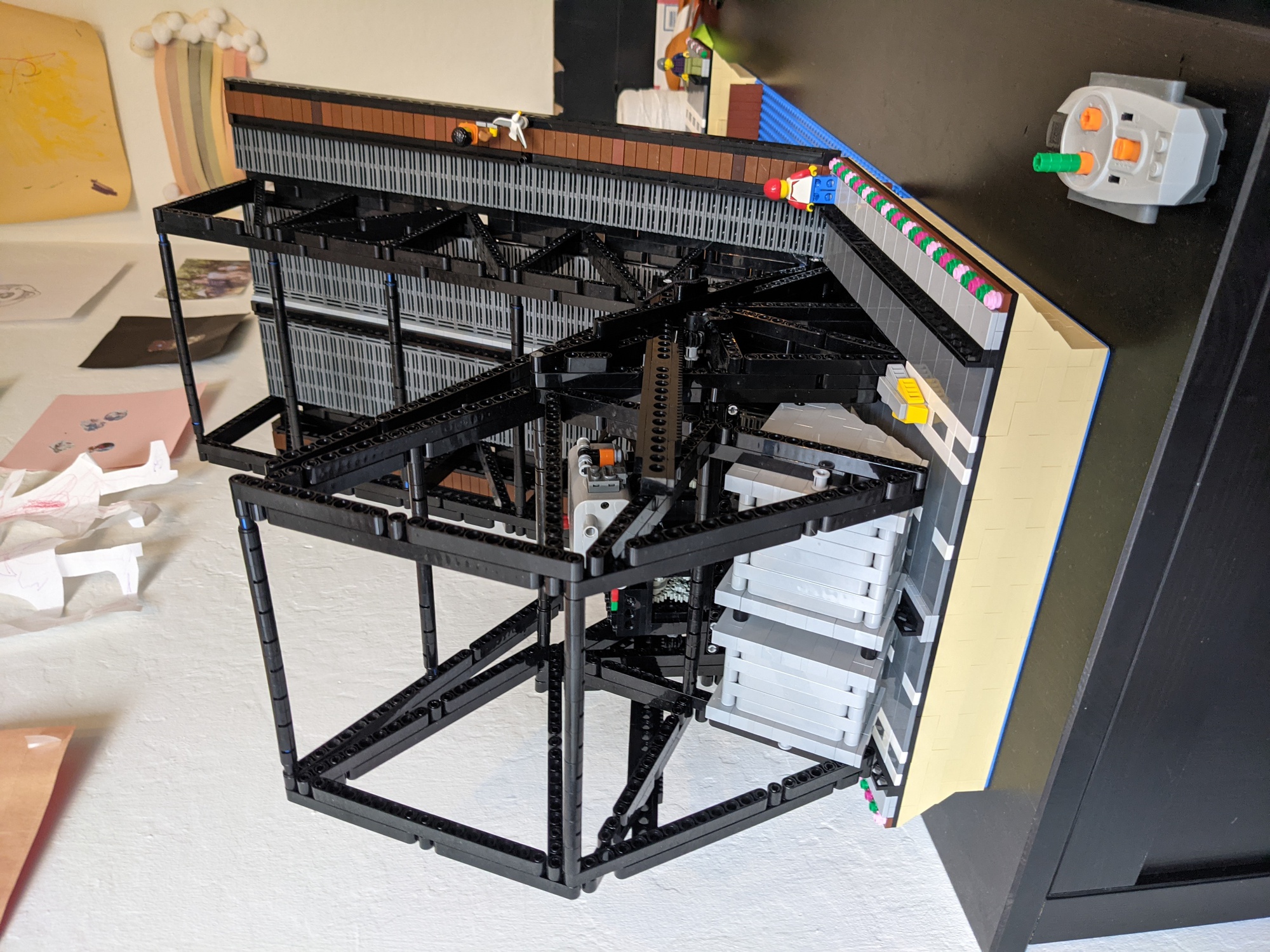
The actual bridge uses connection plates and rivets so that all of the girders at a particular junction can lie in the same plane. LEGO doesn’t provide an easy way to accomplish this, so the truss ends up being multiple layers thick: one plane for the vertical members, one for the horizontal members, and one for the diagonal members, with additional non-structural pieces added to create the illusion of everything living in a single plane.
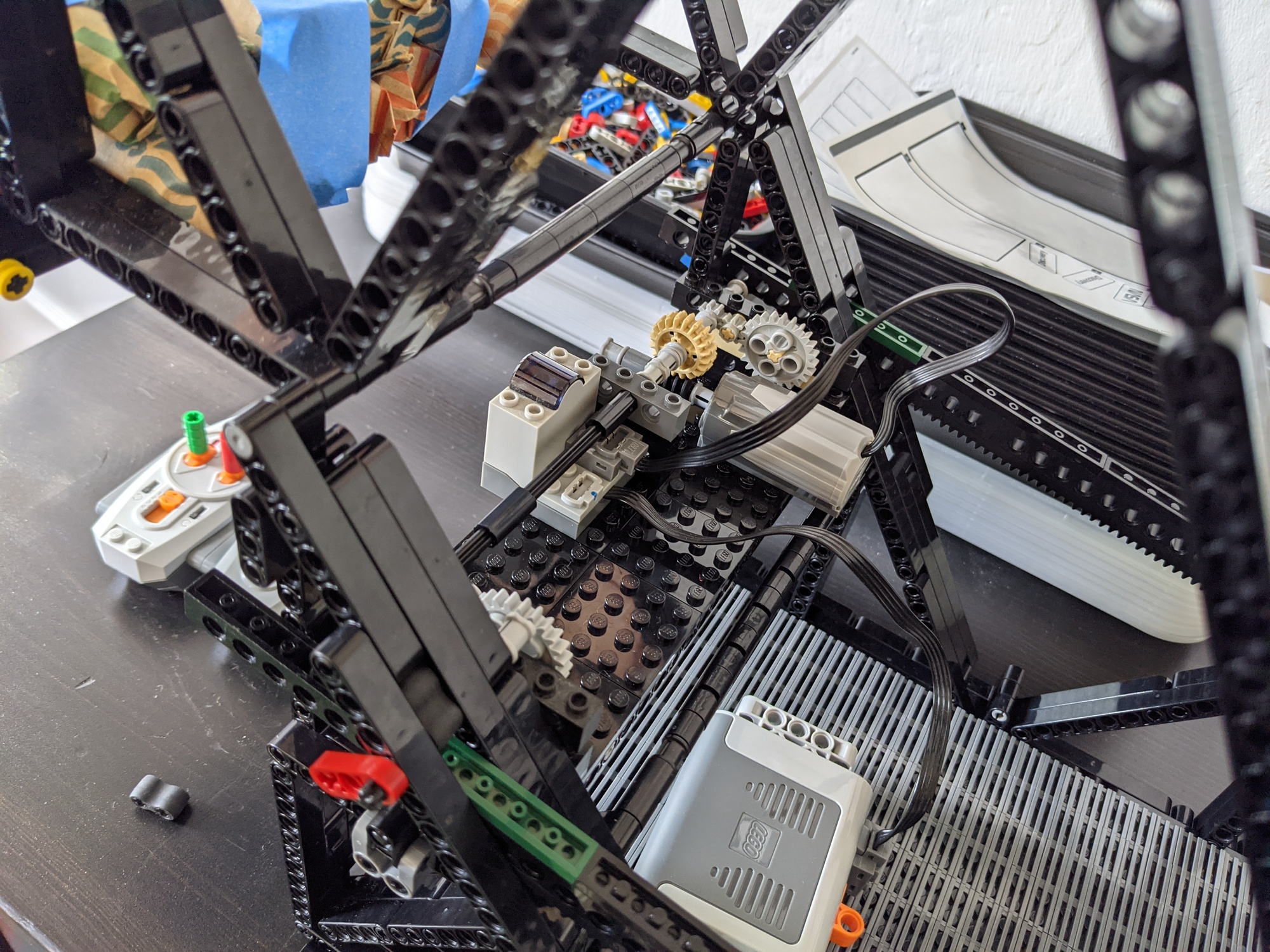
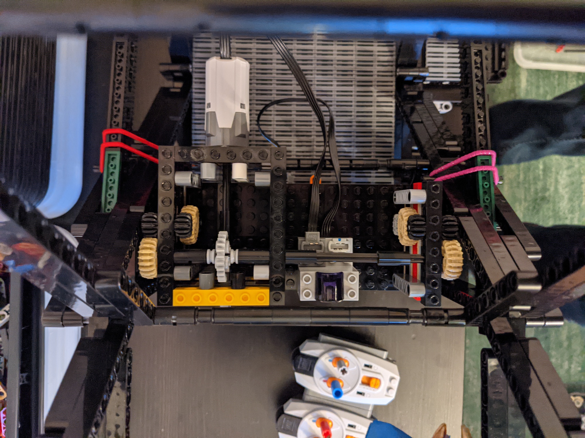
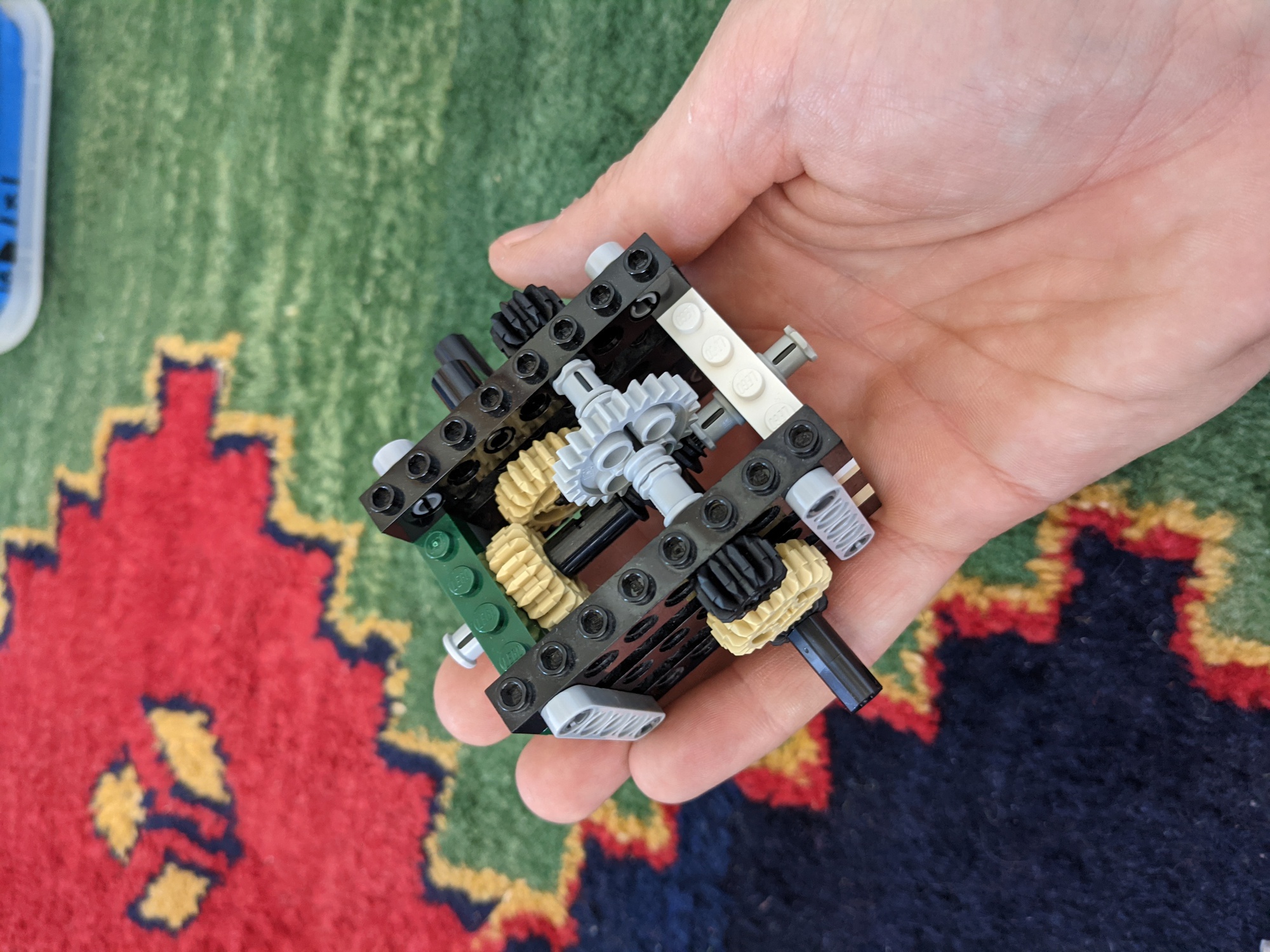
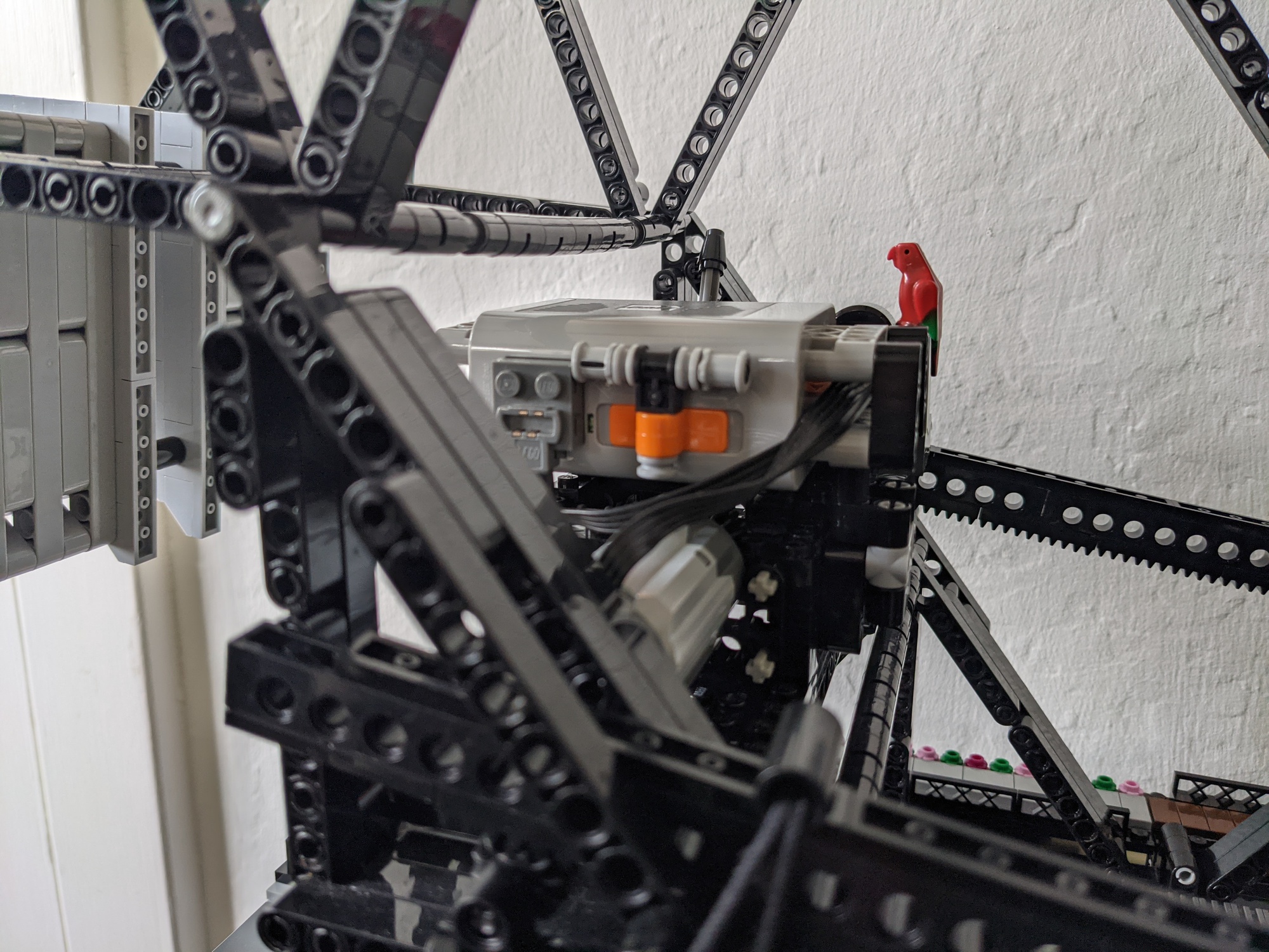
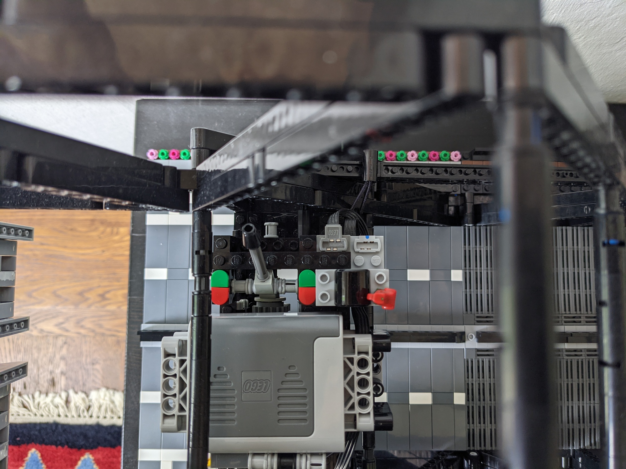
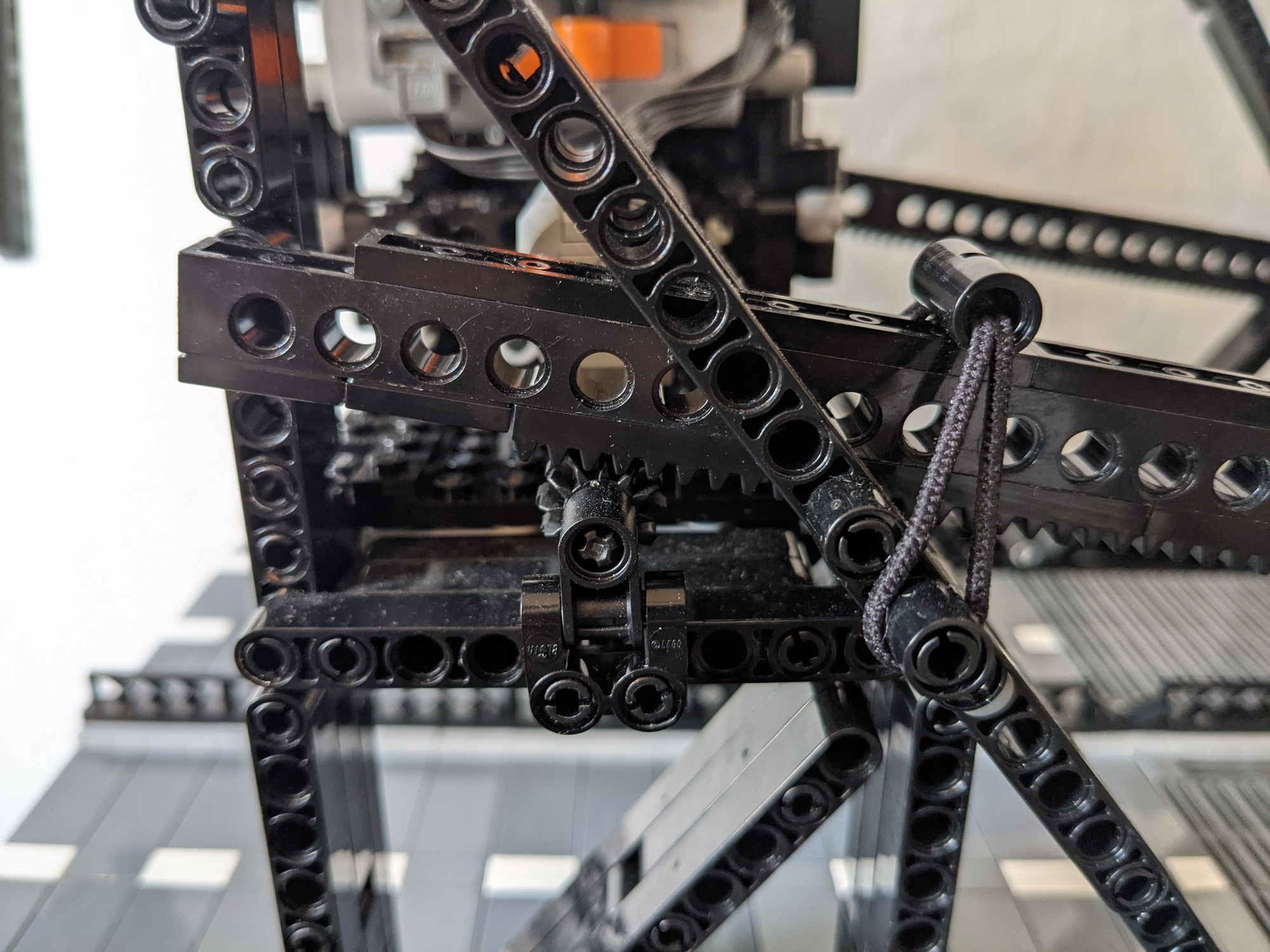
Despite having built many Technic models over the years, it took many iterations to get the gearbox right. The copy of The Unofficial LEGO Technic Builder’s Guide I had picked up years ago at Powell’s Books in Portland, Oregon came in very useful here. The early iterations either took up too much space or failed to provide enough structure to ensure the gears stayed in contact with each other. The gearbox also includes a clutch, so the bridge can be disengaged from the motor for manual operation (flipping the switch to green engages the motor and red disengages it).
Once I had a full-scale model mostly built, I started thinking about ballast for the counterweight. The densest material I had sitting around the house was rolled coins, so I used those for early experimentation and to get a sense of how much weight I would needed. I ultimatedly used copper-plated lead shot as a pourable ballast.

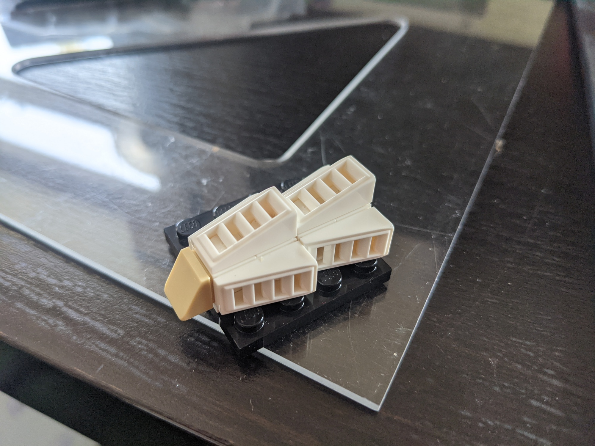
The ballast lives in two hollow boxes (on the real bridge, these are solid blocks of concrete). The unusual trapezoidal shape so that the counterweight doesn’t collide with the road when the bridge is in the open position (a slight simplification of the shape used in the real bridge). The south counterweight is slightly wider (and therefore heavier) than the north counterweight to account for the fact that there is an extra vehicle lane cantilevered off of the south side of the bridge.


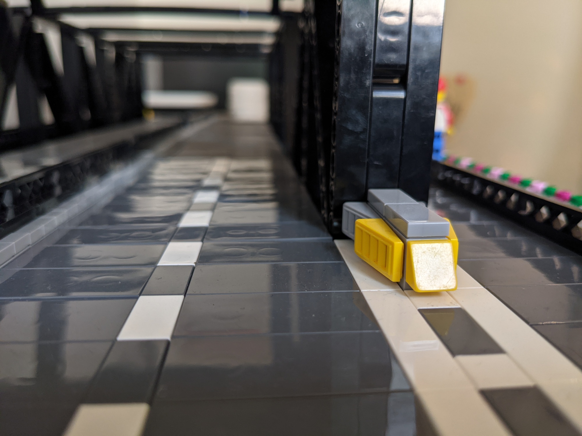
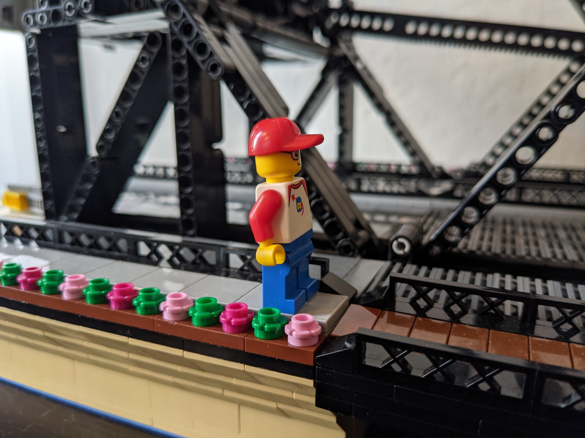
The “impact attenuators” were a fun detail to design.

Other miscellaneous design notes:
- It turns out to be pretty difficult to mix studless Technic pieces with studded LEGO pieces.
- Apart from the ballast, the other non-LEGO parts in the model are the two elastic hair ties that ensure the rack and pinion stay in contact with each other.
Here’s the finished model:
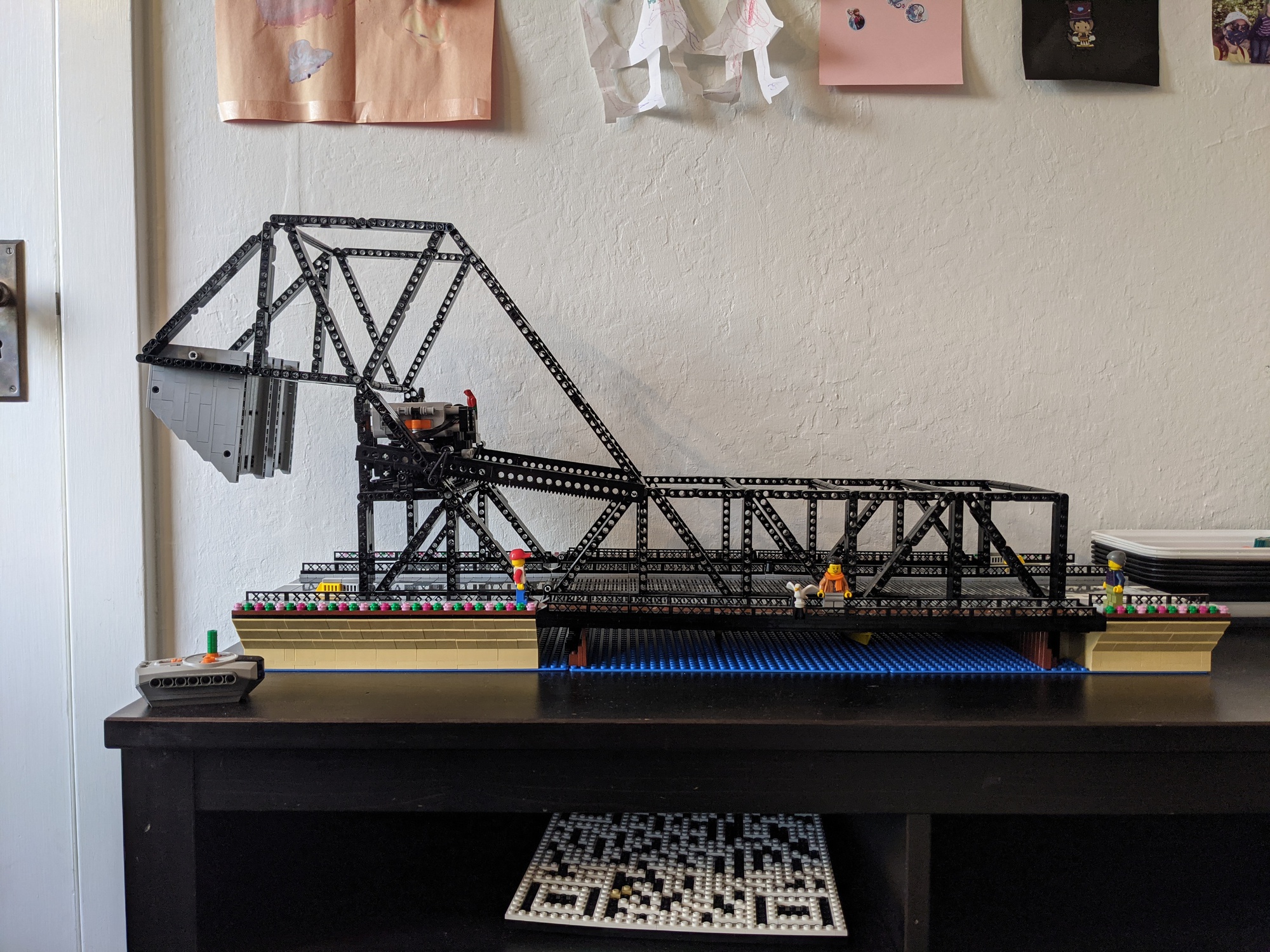

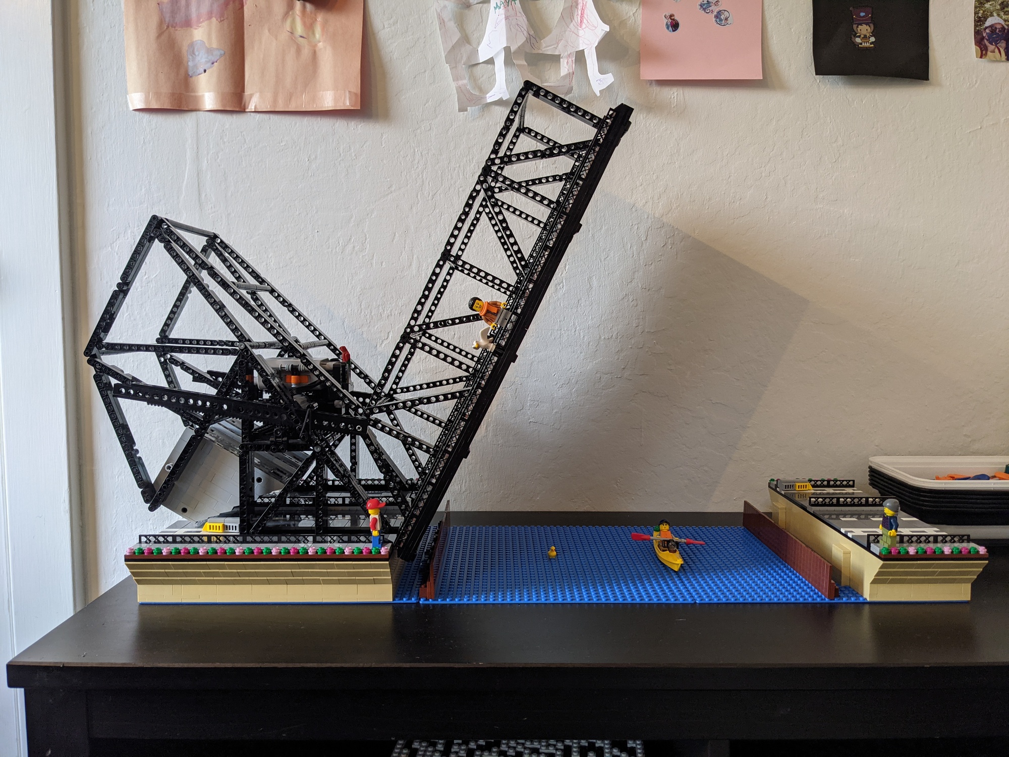
and here’s a video of it in operation.