I was inspired to attempt to build a working LEGO pin tumbler lock after rekeying the locks to my house.
After hitting on the idea of using 30° 1x1 slopes to recreate the diagonal slopes of the key itself, I checked if others had tried a similar project and found this video, in which the builder used the same approach for the key. This was a nice confirmation of the overall approach, and it also got me thinking about using axles for the pins.
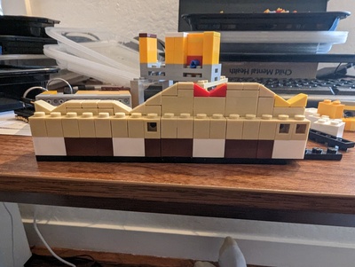
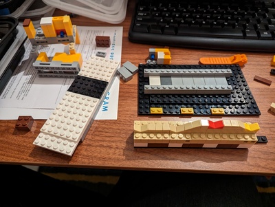
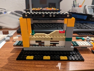
An early design goal was to make it possible to rekey the lock (by changing both the height of the key and the lengths of the pins). The final model makes it easy to change the key, but changing the pins requires some tedious disassembly.
The assembled key consists of:
- A long base with black and white areas indicating where specific types of modules need to be added. The left end of the key a fixed slope that is low enough to pick up the pins. The right end is a handle.
- 5 pin receptor modules. There are 3 available variants, each with a different height, and the choice of these determines the “code” for the key.
- 4 transition modules. These provide smooth transitions between the receptor modules.
- 1 lead transition module. This provides the transition between the first receptor module and the slope at the front of the key.
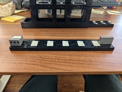
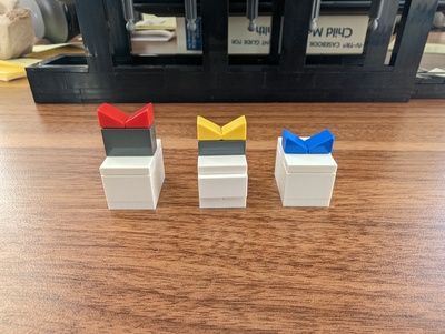
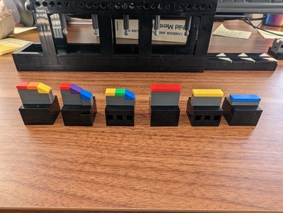
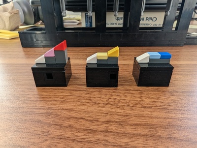
To assemble the key, you add the 5 receptor modules, then the 4 transition modules, and finally the lead transition module.
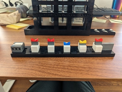
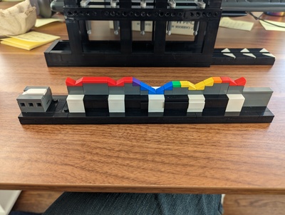
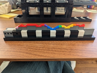
The modules are color coded to provide an additional visual check that the key is correctly formed. If there is any discontinuity in color (e.g. a red piece directly touching a blue piece), it means there is a discontinuity in height, which will cause the key to jam on the way in or out. A color is allowed to touch itself, an adjacent color in the 6-point color wheel (e.g. red to purple or orange), or a lighter/darker version of itself (e.g red to pink or pink to white in the lead transition module).
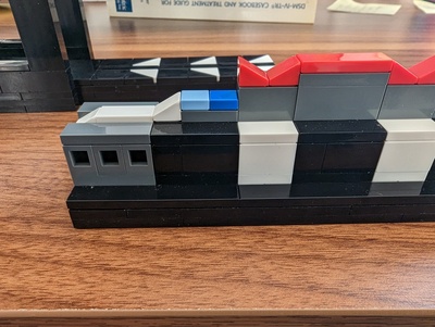
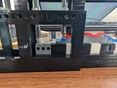
Inside the lower half of the lock, 5 pins of 3 different possible lengths are created using axles of 3 different lengths (5L, 5.5L, and 6L).
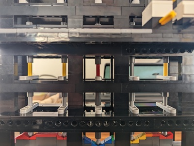
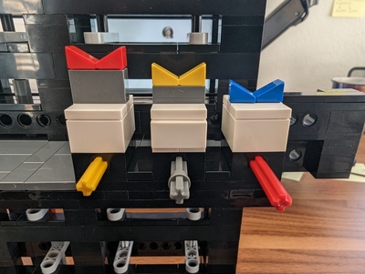
To “open” the lock, you rotate its upper half toward you, shifting the upper set of pins to be out-of-plane from the bottom set of pins.
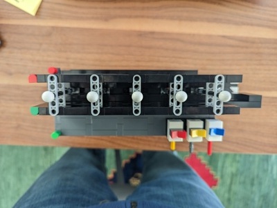
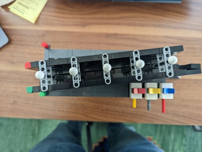
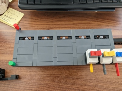
The key opens the lock if and only if each pin receptor module matches its corresponding pin/axle length. A guide on the side of the lock illustrates the correspondence if you don’t want to resort to trial-and-error (there are 5 pins and 3 possible heights, so 3^5 = 243 possible keys).
If a given receptor module is too tall, the lower pin extends upward into the upper half of the mechanism, preventing it from rotating open; if the receptor is too short, the upper pin extends into the lower half of the mechanism, also preventing rotation.
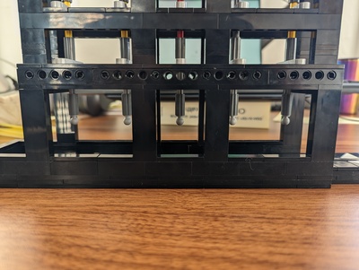
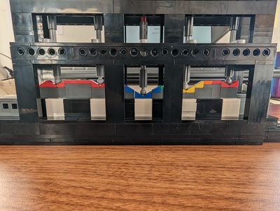
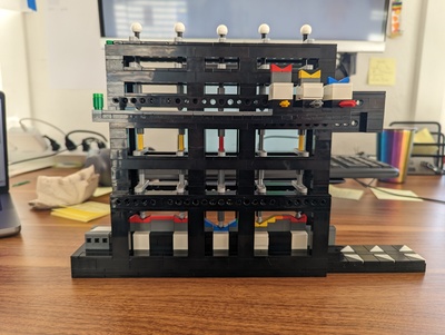
Here’s a video of the entire assembly in action:
A few other design notes:
- The idea of using headlight bricks to create smooth slopes comes from this slide deck. Fun fact: the stud on the side of a headlight sticks out just barely past where the vertical surface of a normal 1x1 brick would be; this fact required making the track for the key a bit wider than the key itself (I eventually opted to cover the studs with tiles anyway).
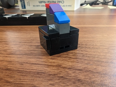
- The idea of using a Technic tow ball piece at the end of each pin to follow the surface of the key came from this thread (which also includes the creator of the video I found earlier). The spherical surface of the tow ball minimizes the friction between the pin and key, preventing the mechanism from jamming as the key slides in. I also used tow balls on both sets of pins where they meet. This gives the system just the right amount of tolerance: enough to open if the key shape is correct (even if the pins are very slightly out of alignment – the inverted tow ball can “climb” slightly up the slope of the upright tow ball), but not enough to open if the key shape is incorrect.